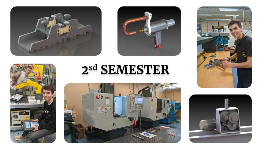
INTRODUCTION
After a successful first semester full of new knowledge, I was always eager to see what I would discover and learn. This second semester was a rich one, covering a wide range of subjects such as robotics, manufacturing, modeling and APEF (avant projet d’étude de fabrication).
PROJECT 2.1 — Process selection and costing
During this SAE we had to prepare a part for production for a series of 1000 parts. For this, we were each given a different part with different production solutions. For my part, I was offered a fixture (pictured below).
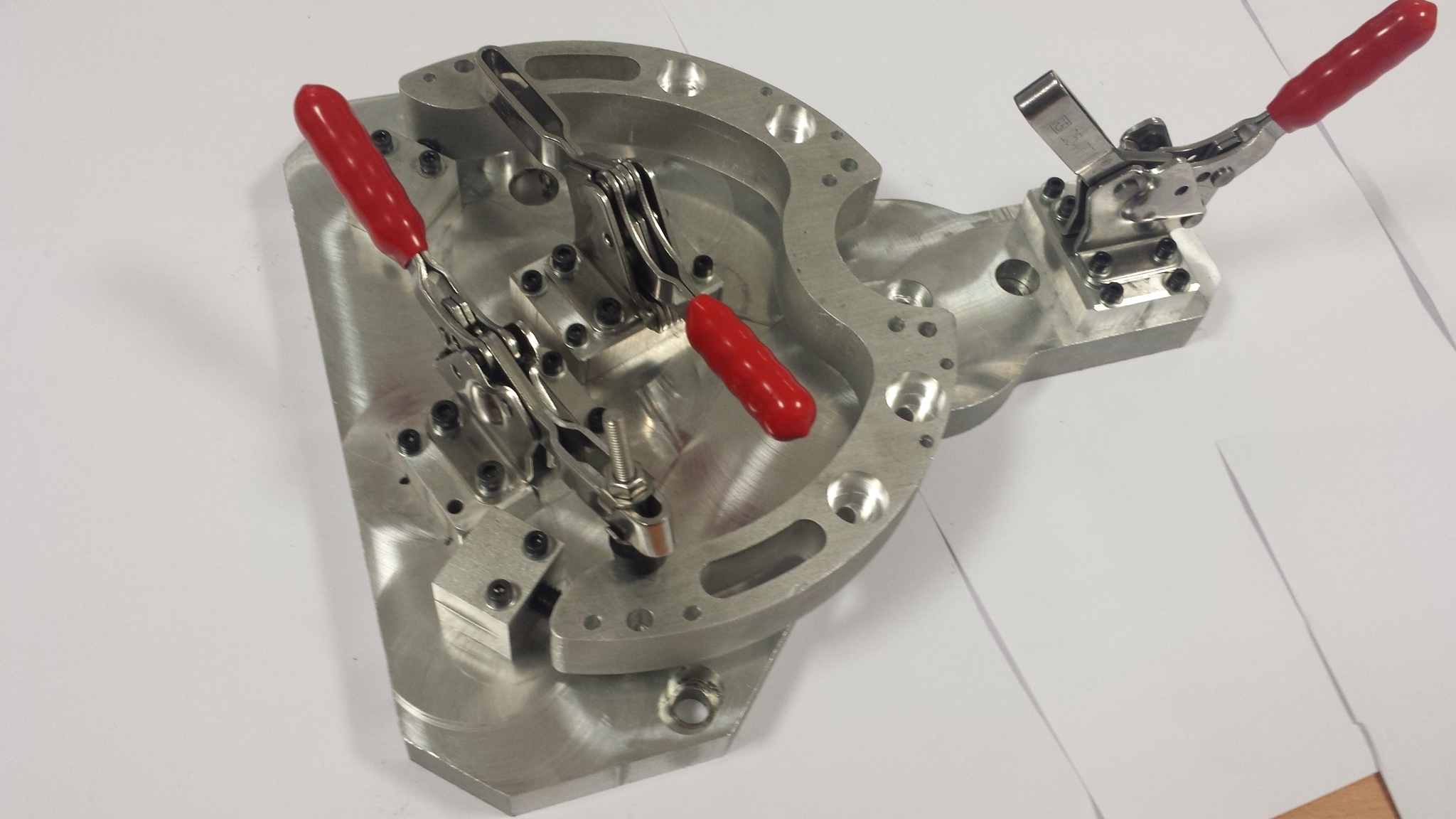
For my part, I had a machined part, but the raw material came from the foundry. We had a drawing of our parts with the tolerances. So we had to determine whether the tolerances were achievable with our means of production and determine the number of phases needed to produce the part within maximum tolerance.
Initially, I had determined 3 phases, but after several analyses of the part, I optimized the process and succeeded in producing it in 2 phases.
I also had to determine the production time and cost for a small production run of 1000 units.
PROJECT 2.2 — Automated gluing project (ROBOGUIDE)
This SAE enabled us to put our robotics courses and practical work into practice.
Our challenge was toautomate the gluing of fittings to plates, using the most suitable robots, and to do it as quickly as possible.
This SAE was carried out 50% of the time on my own, which wasn’t easy at first, as I hadn’t yet mastered the software (ROBOGUIDE).
First of all, I determined the robots to be used for the various actions (picking up the plates, picking up the fittings and applying the glue). Then I modeled the supports for the plates and fittings.
Once this work was done, I was able to move on tosetting up the robots and configuring their parameters.
Video result of my implantation
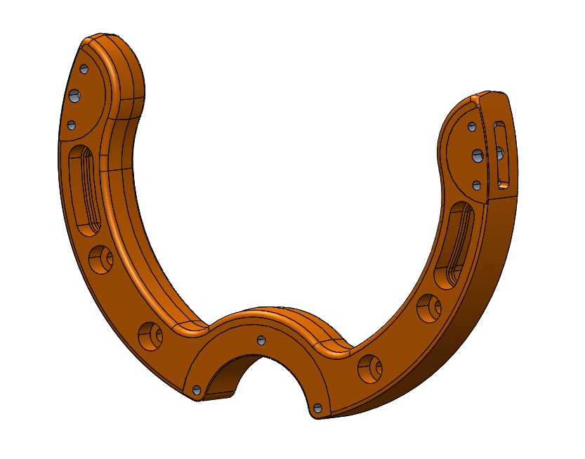
PROJECT 2.23 — Production of a fusible component
During this SAE we carried out a study to design a fusible part for a helmet chinstrap. The helmet had to comply with standards for both work use (on a building site, for example) and bicycle use. A system was needed to switch from one use to the other.
Our part had to break between 600N and 1000N.
We had several notches proposed with their associated abacus.
For our group we have chosen this one:
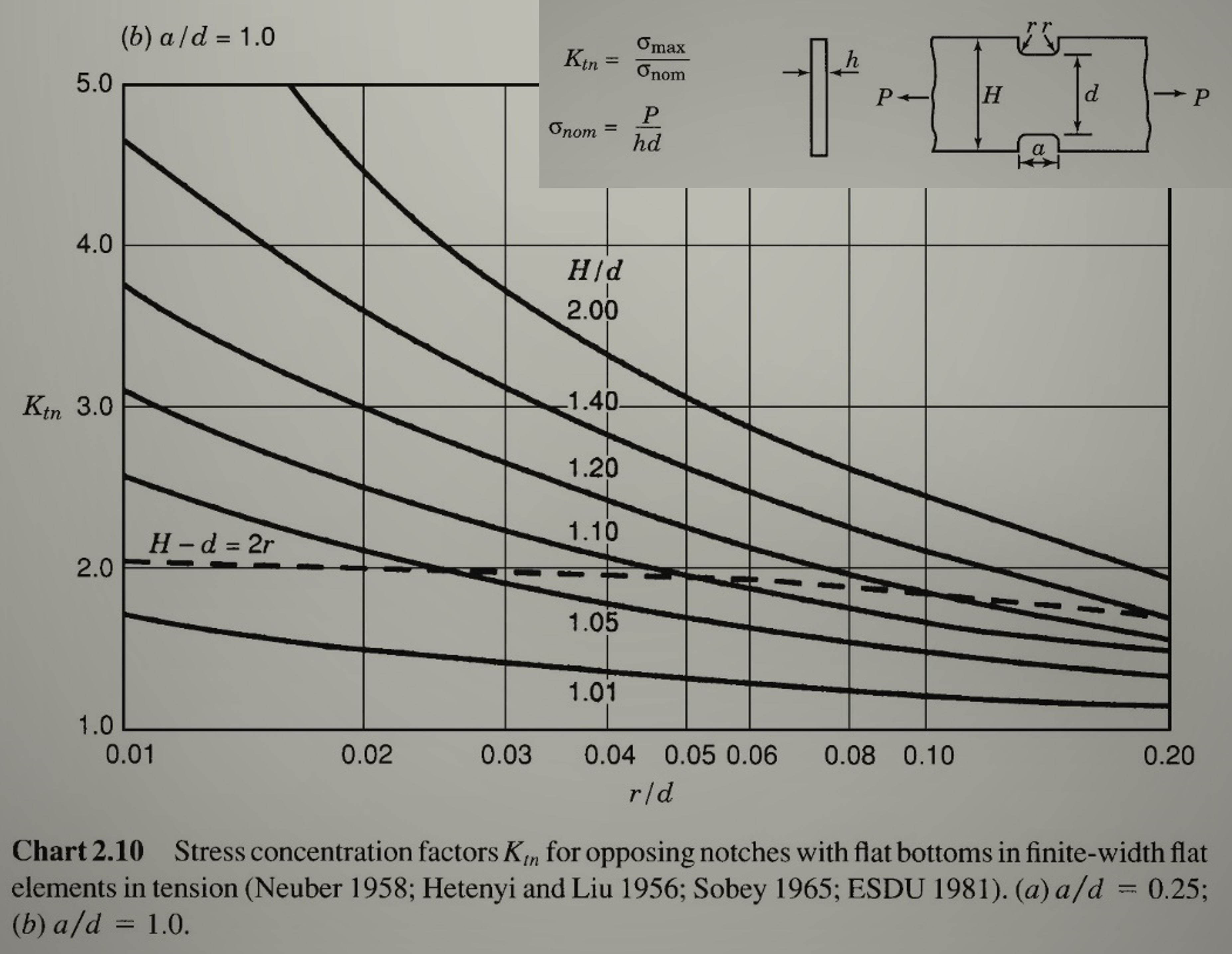
First, we thought we’d determine the Kt that would allow our fuse to break at 800N. But after modelling and testing, the result obtained was not satisfactory (rupture at 600N). So we decided to take a different line of reasoning: we took a Kt value, then calculated the dimensions of our fuse using this value. And finally to see if the dimensions we found would enable us to make a fuse adapted to the existing system (max width = 6.8mm).
To make it easier for us to choose the Kt, I made an Excel table that automatically calculates the values of the various parameters according to the Kt chosen. The most time-consuming part was transcribing each value from the abacus.
Despite our numerous calculations, the tests were inconclusive. We concluded that the abacus given was not suitable, so we chose the dimensions of our fuse on the basis of other tests.
Report poster
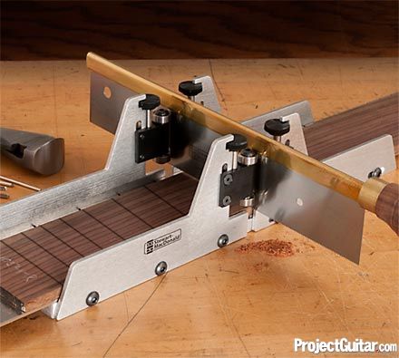
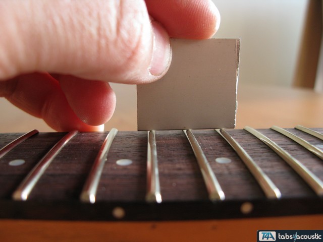
PROJECT 2.5 — Luthier’s mitre box
SAE major of this semester, demonstrating a project. For this one, I was working in pairs. Our subject was “a luthier’s miter box” (image 1), the role of this tool is to guide a saw to make very small and precise slots for adding guitar frets, metal blades on the neck (image 2). To carry out this project, we were given a sample image from the Internet and a 3D model, but this was made for 3D printing, so it wasn’t of interest to us.
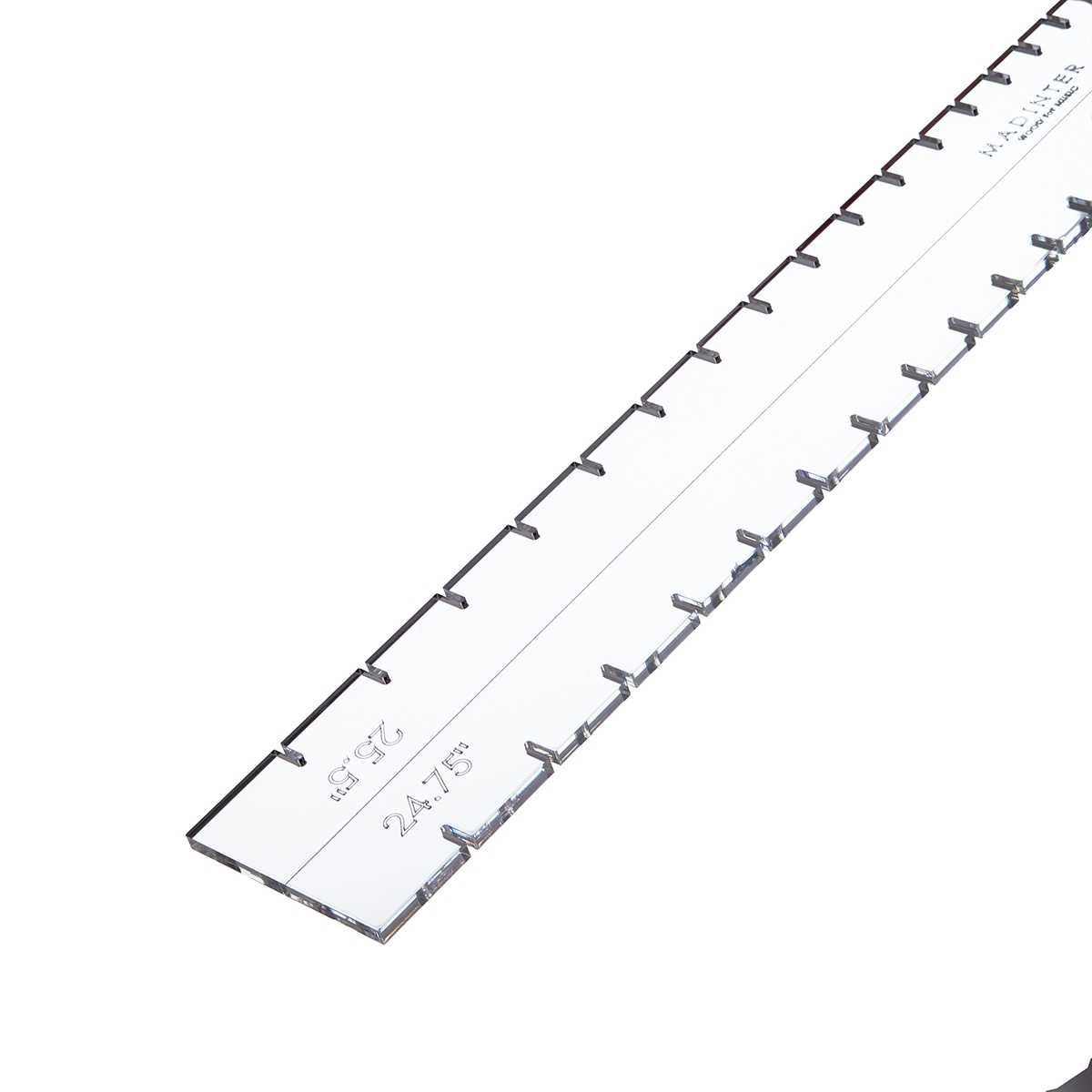
First, we did a lot of research to find out what the standard dimensions were. Such as the height and thickness of a saw, and the dimensions of a jig (image 3).
To model our box, we started with a front-view image, scaled it in SolidWorks and transferred it to the model. Some parts were taken from off-the-shelf items (knurled screws, screws, bearings, etc.) that we bought after modeling.
Once the CAD had been validated by our teacher, we moved on to the documents required for production (definition drawings, phase contract, CAM, rough dimensions, etc.).
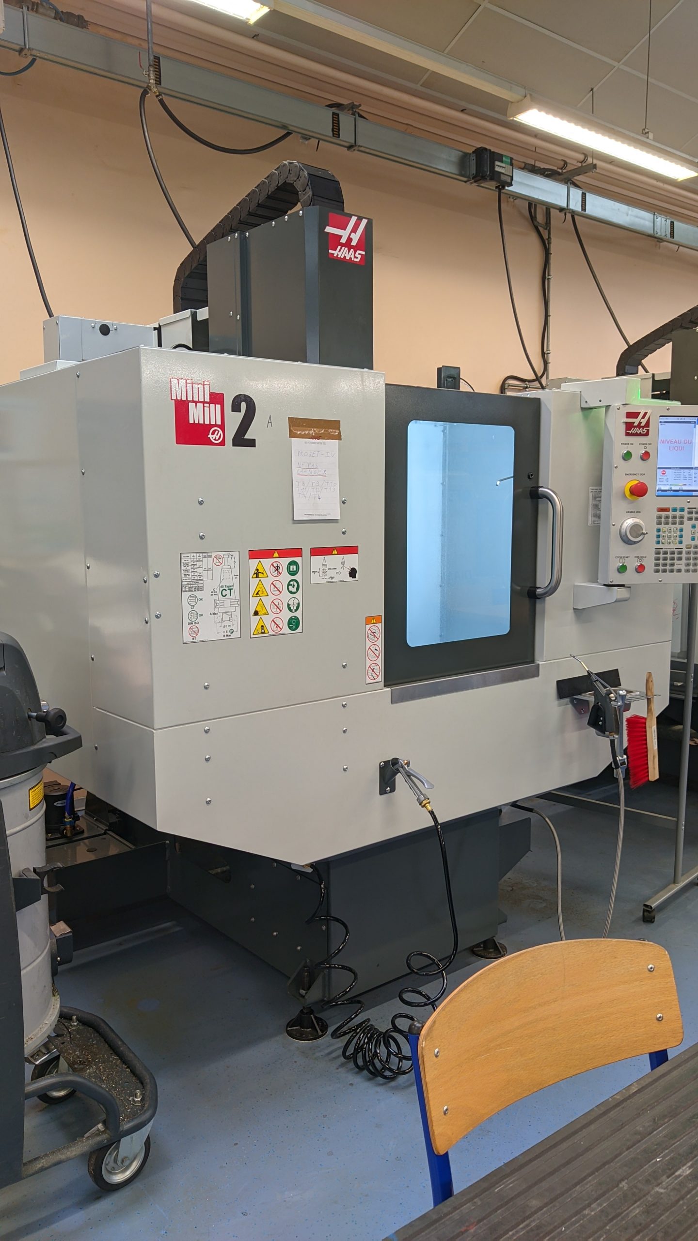
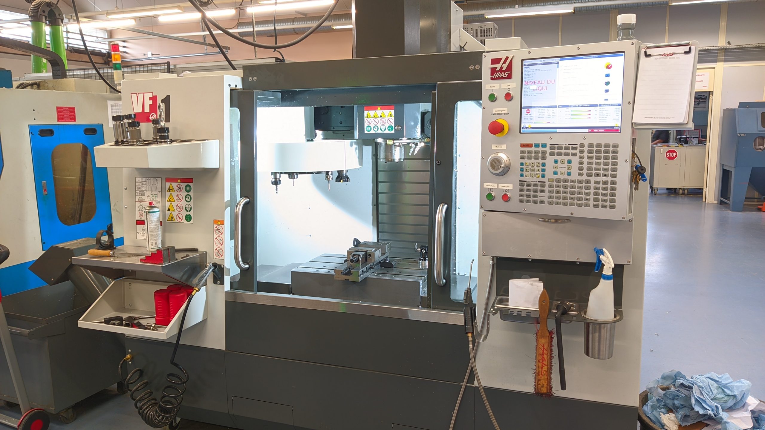
Themachining of our solution went very well, and we were able to discover water-jet cutting as well as 2 new milling machines, the Mini Mill 2 and the FV1 (pictures below).
This first experience of a big project, which lasted a whole semester, enabled me to face up to many difficulties, such as time management andorganization. But we managed to overcome these obstacles.
I gained autonomy in the use of the milling machines, which enabled us to catch up a little. I improved my CAM skills on TopSolid and discovered a new technology with HELICOILS. And of course, we were able to understand and implement the manufacturing cycle of an object.
Many thanks to Ms. Vazquez, who supported and encouraged us in this project.
MY WORK OUTSIDE THE PROJECTS
3D Modeling
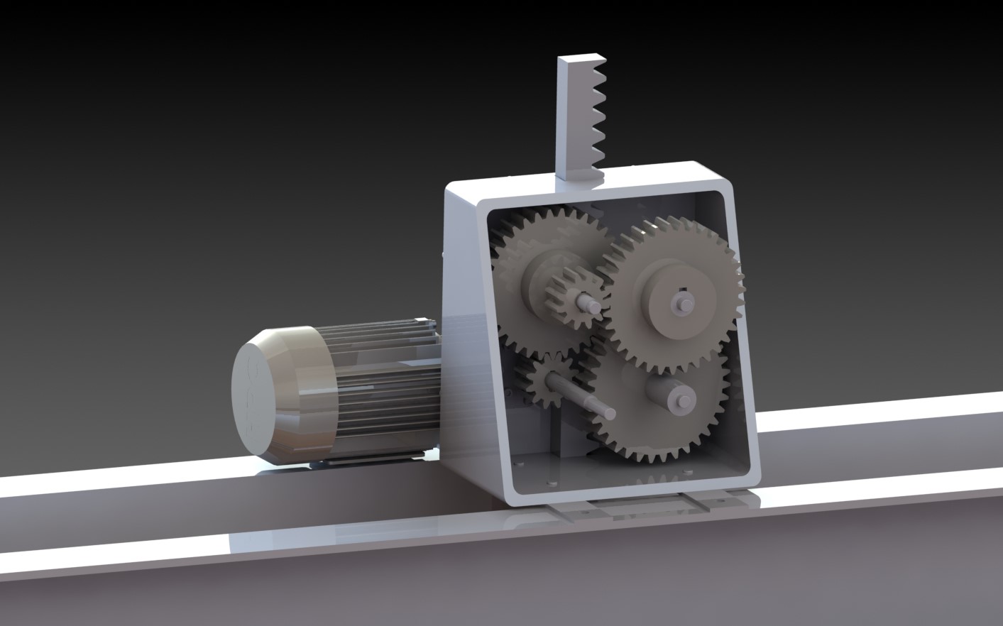
This project involved the motorization of a river discharge gate. We were given the necessary gears and rack.
I had to choose the motor with the right power. To do this, I determined the input torque according to the output torque (rack) as well as the torque produced on each axis to size the keys.
We also had to make our crankcase as compact as possible.
Not very complex in terms of design, but very interesting when it comes to improving an existing system.
Welding pliers
This 3D modeling project was interesting enough to develop our knowledge of the software (SolidWorks) and complete in its content; a mix ofelectricity, simple mechanics and means of production (molding a hull and sheet metal work) that we had never used on SW.
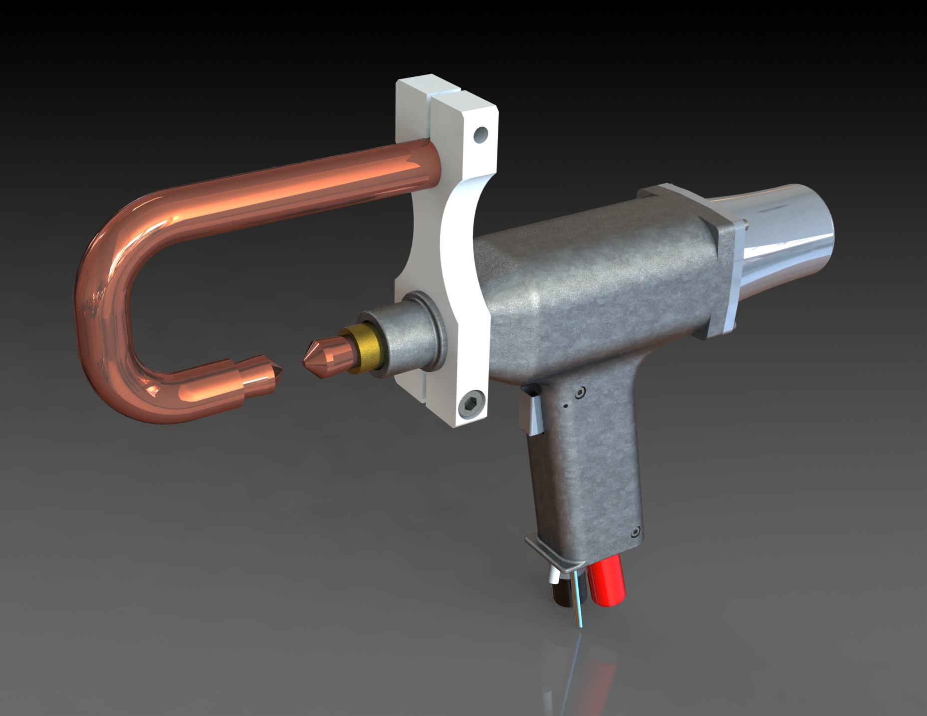
We had to model a spot-welding gun driven by a pneumatic system.
We had to carry out electrical calculations to determine the voltage needed to weld 2 sheets of 0.7mm thick, the generator consumption and the cost of use (welding price).
Next, we calculated the diameter of our piston in relation to the pneumatic pressure supplied. Using this data, we determined the dimensions of our return spring (the IUT software, “MenuMeca”, determines the dimensions of a spring according to input parameters).
The interesting part of this project was the realization of the shell , which had to be ergonomic yet moldable. The sheet metal work was pretty straightforward, but I had a lot of fun making an aesthetically pleasing trigger.
The wiring function on SW is very hard to get to grips with. I’ve encountered numerous bugs and difficulties in getting my cables through my system correctly.
Industrial Project Organization (IPO)
We had a project to create andoptimize a workshoplayout.
To do this, we were given a subject with lots of instructions and data. It was very important to have all the data in mind, because setting up a project like this requires a lot of time to think about andimprove our solution. We mustn’t forget a single piece of information that could completely change our results.
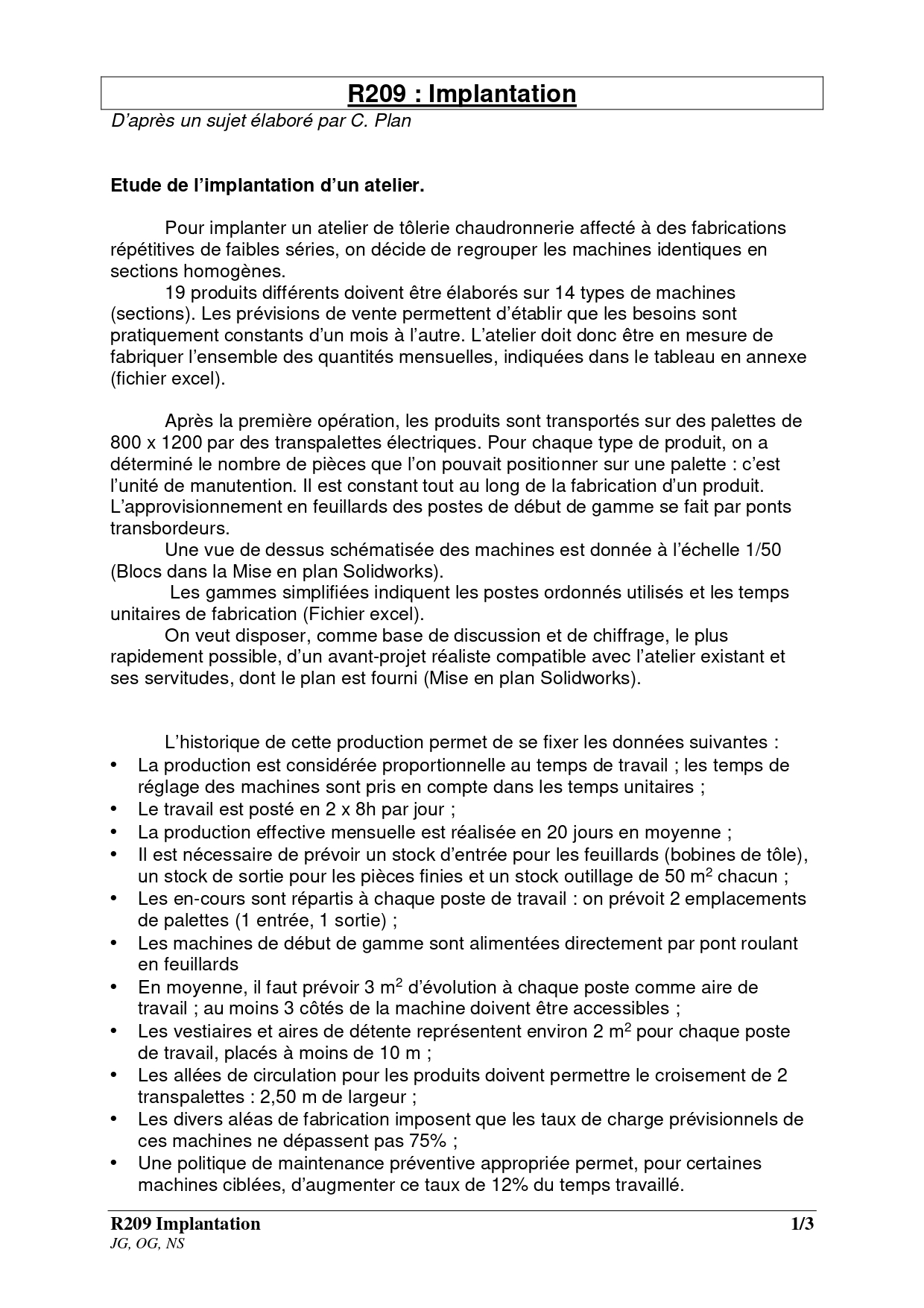
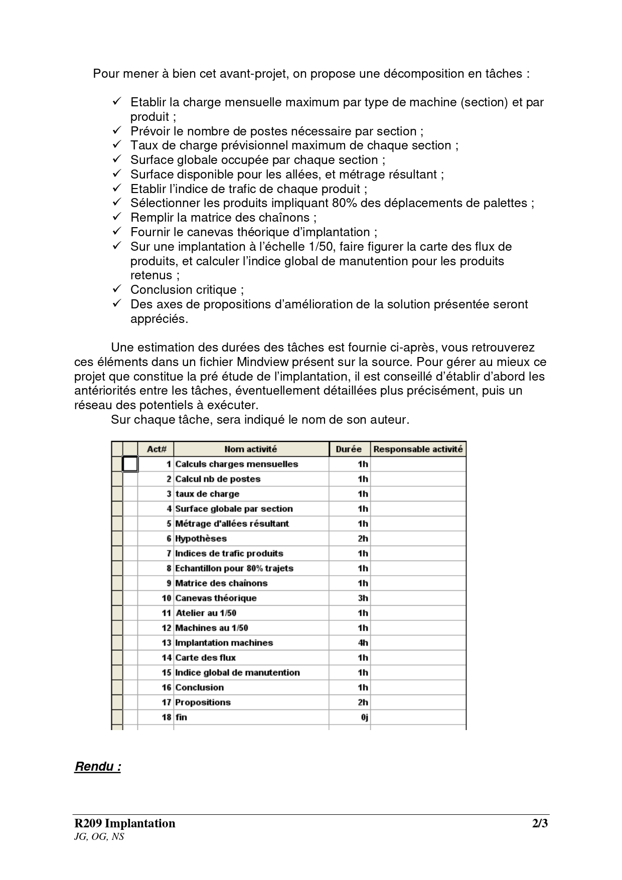
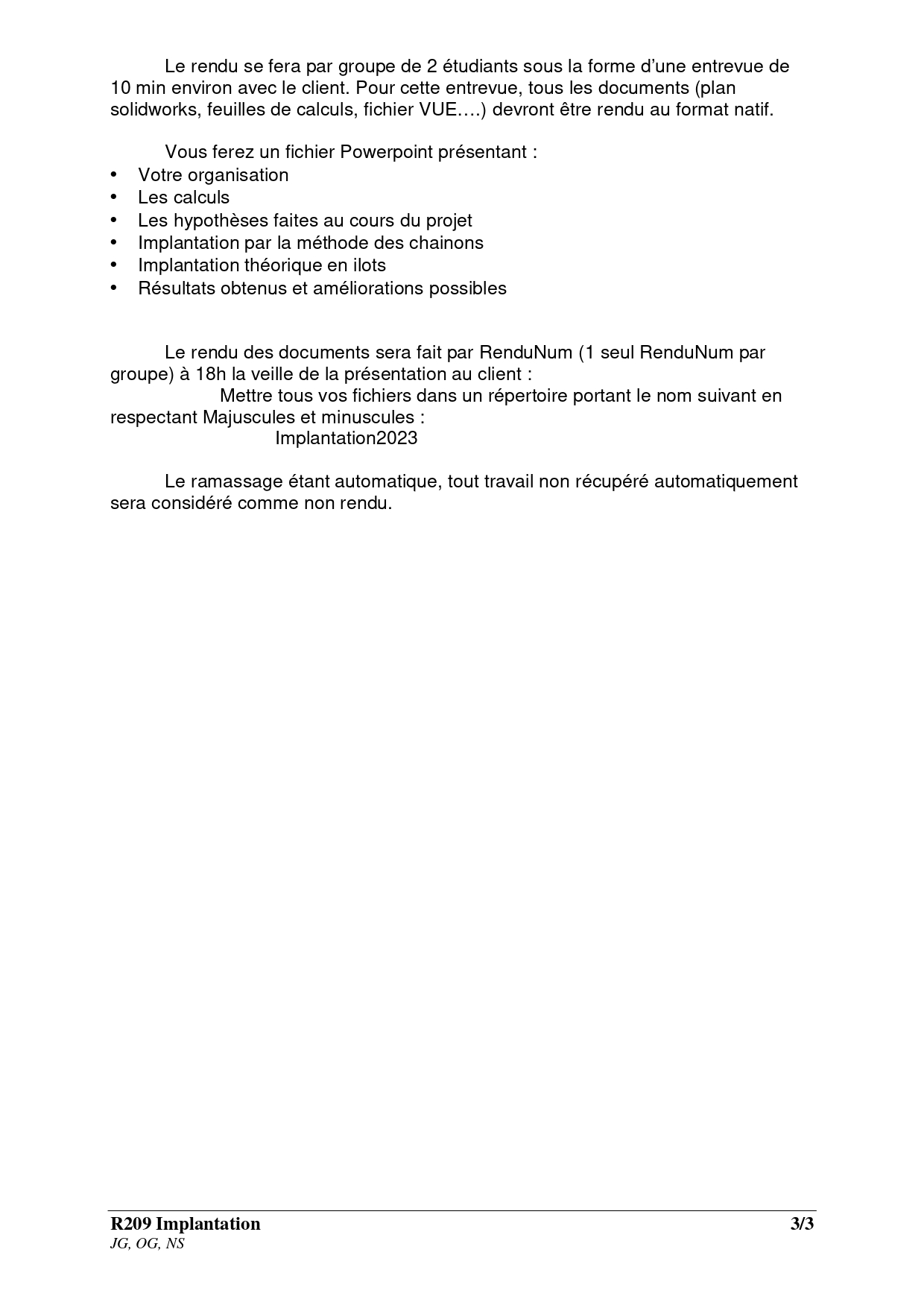
Subject of the implantation
Initially, we processed the data for the future workshop to get an overview of flows and loads. An Excel file was made available to us to process all the data.
Thanks to this initial study, we were able to determine the number of stations required per section, the surface area of each section, the length of the aisles and thetraffic index for each product.
Then we could move on to a theoretical framework, followed by a layout of our workshop on SolidWorks.
This work demanded a great deal of rigor and reflection in order to constantly improve our implementation. It’s a job that requires us to go through many test phases, and we designed 4 implementations before having the final version, which could itself be improved.
Podcast project
We were lucky enough to be able to work with members of the Radio France team to create a podcast, the theme of which this year was the scientific image.
Initially, we were due to interview Anne-Lyse Renon, designer and doctor of social sciences at the Ecole des Hautes Etudes en Sciences Sociales. Unfortunately, she was unable to be available on the day of our meeting.
However, we had already had the chance to exchange views by videoconference.
Thanks to our teacher and Radio France contributor, Philipe Baudouin, we were able to learn the basics of podcast production.
Our class was divided into 2 groups: technicians and interviewers. We learned the meaning of the different signs used during a recording or a live broadcast (comma, cut the mic, take the mic…).
Our job was also to prepare our data sheet (questions, names of interviewers, themes, credits…).
Our guest was unavailable, so we interviewed our radio teacher, Mr. Baudouin, who has done research on the paranormal and the impact of the scientific image on it.
This new experience was veryenriching, despite the fact that it wasn’t easy to take on the intonation and speech of a journalist.
End of this year
To conclude this first year, a day was organized to present the projects of all1st year students. There were also two competitions, the first pitting music boxes against each other (melody, mechanism, aesthetics) and the second a dragster race propelled by a rubber band.
Finally, volunteers were invited to help tidy up and clean the workshop. It was a big afternoon of cleaning for around twenty of us, with the cleaning of the water-jet cutter, 3 milling machines and the sorting of numerous tools.
By mid-April I had also found a work-study position in the design office as a tooling designer at Airbus Helicopters in Le Bourget.
This year has been full of discoveries anddeepening of my personal knowledge. I’ve learned a lot and discovered exceptional teachers who listen and are very human.
Enthusiastic about coming back next year and applying my skills in business.