
INTRODUCTION
September 2022, back to school at the IUT de Cachan in GMP. Discover the world of higher education.
Having just graduated from high school, I’m entering a whole new stage in my student life. During this first semester, I’ve been able to learn the basics of mechanics (statics), SDM, production, modeling and many other notions, which are put into practice via SAEs (Situations d’Apprentissages Evaluées). So in the first part of my portfolio, you’ll find all my work and personal feedback on my work.
Enjoy your reading
PROJECT 1.1 — TECHNICAL SPECIFICATIONS
Our very first task as a group was to respond to HKW-AERO’scall for tenders to test the spar for their brand-new two-seater. To do this, we drew up a set of specifications.
So we had to find out how to draw up specifications.
First of all, we found out about the company and their new aircraft, so that we could give a brief background presentation. Then we set out the proposed objectives , such as the dimensioning of the distribution of forces and the various constraints (weight of the coupling, means of production, etc.). We then presented one of our solutions and the means to achieve it (calculations to be carried out, production method…) as well as a provisional schedule.
PROJECT 1.2 — PROJECT DESIGN STUDY
Once we had designated the project, we implemented the necessary steps to prepare the production of our technical solution in line with our specifications.
To this end, we have performed various calculations in an Excel spreadsheet to obtain results that will be dynamic according to the input data (chosen by the user). The results of these calculations will give us the dimensions of the various parts of our hitch.
So we determined the values of the various forces according to the distribution requested by the user. With this data, we were able to draw up a graphical representation of the force distribution. But above all, we were able to determine the length of each spreader bar, as well as the position of the various holes that will be used to assemble the hitch.
As part of our brief, we were asked to produce iso-tensioned spreader beams. To do this, we carried out the various calculations and produced a graphical representation of the spreaders.(SDM)
Then, to complete our calculations, we looked at the size of the tie rods according to the force exerted in traction. Since the force was so low, the tie-rods could be any size.
To illustrate all the calculations, I’ve created a graph showing the spreader bar coupling with the calculated dimensions.
MODELING — SOLIDWORKS
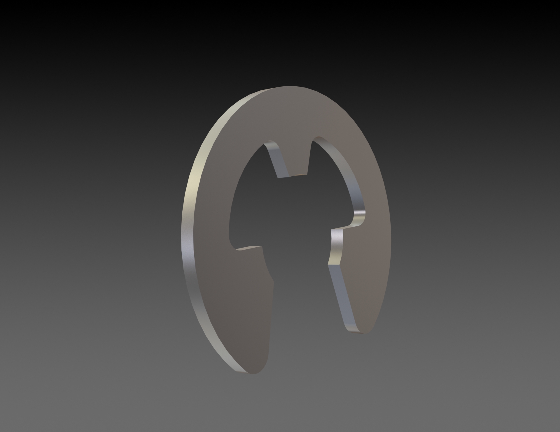
In designing our solution, we were faced with a number of constraints. Firstly, we had to use several manufacturing processes, including turning, milling, punching, bending and laser cutting. Secondly, we had to make at least 1 spreader bar with an iso-tensioned shape. For the spreaders, we could choose between 20×20 square tubes, 3mm medium, 2mm aluminum sheet or 1.5mm steel sheet. For the tie rods, we could use 3mm medium , 2mm aluminium or 1.5mm steel. To connect the tie-rods and spreaders, we could choose between Ø6mm circlips or Ø5 or 6mm nuts.
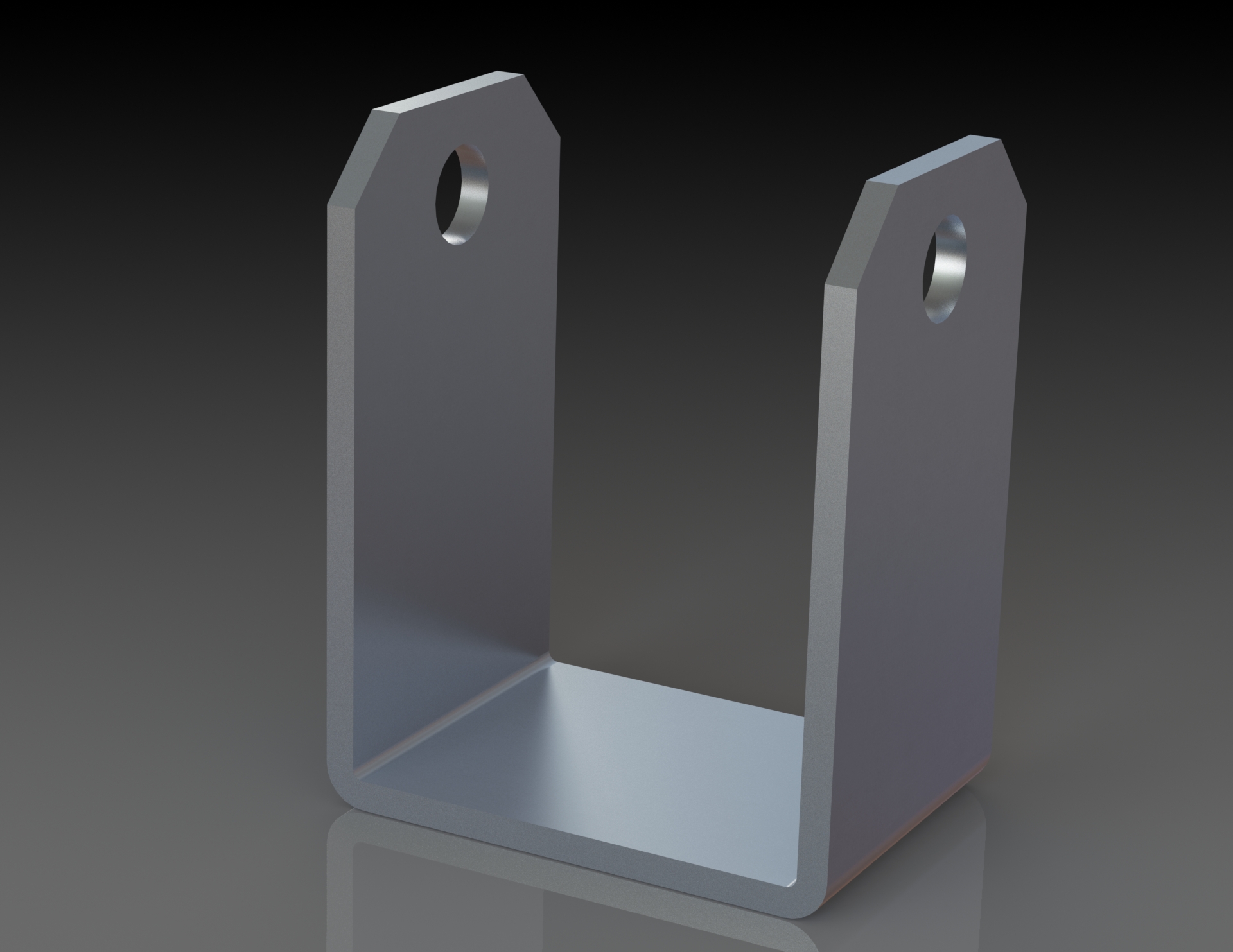
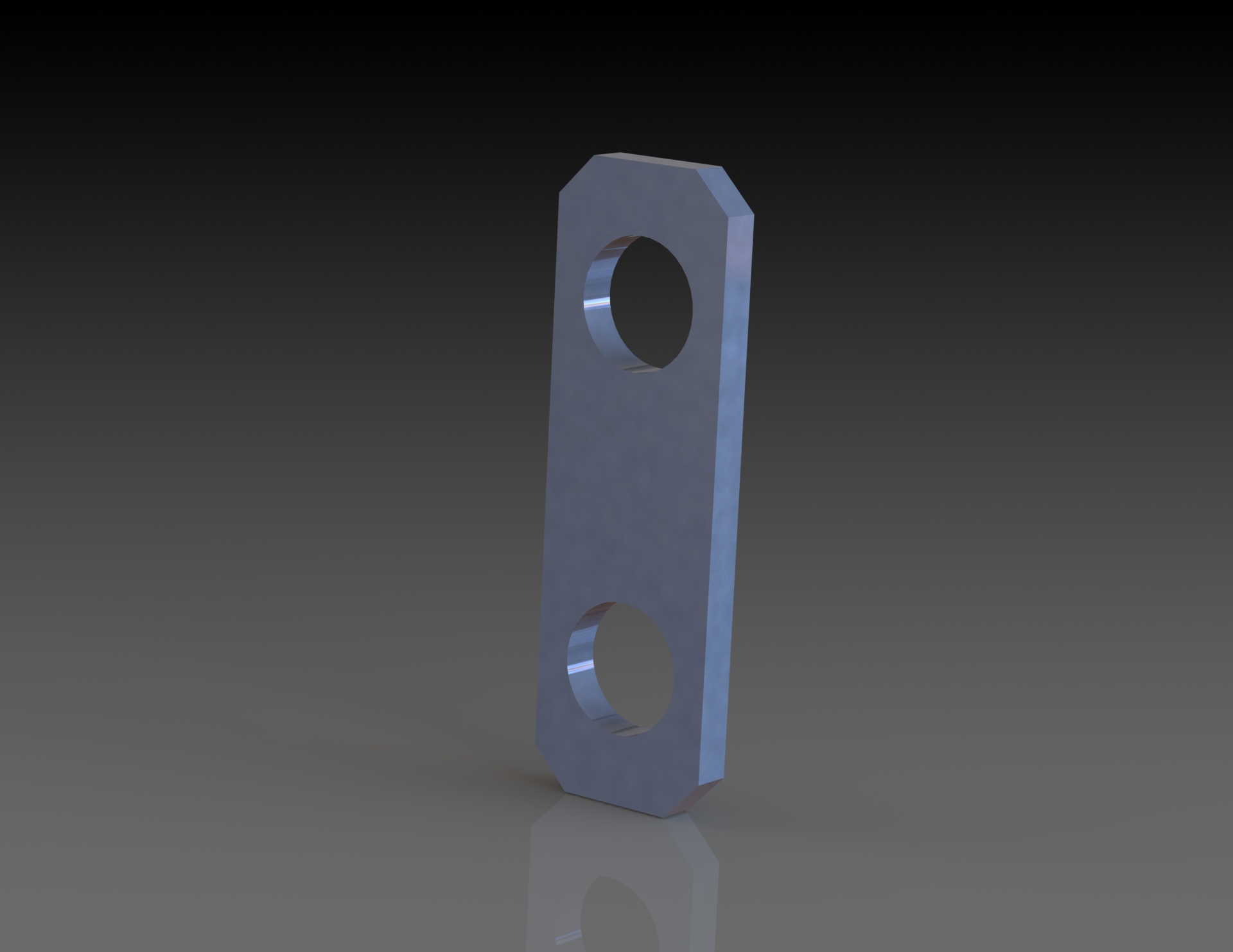
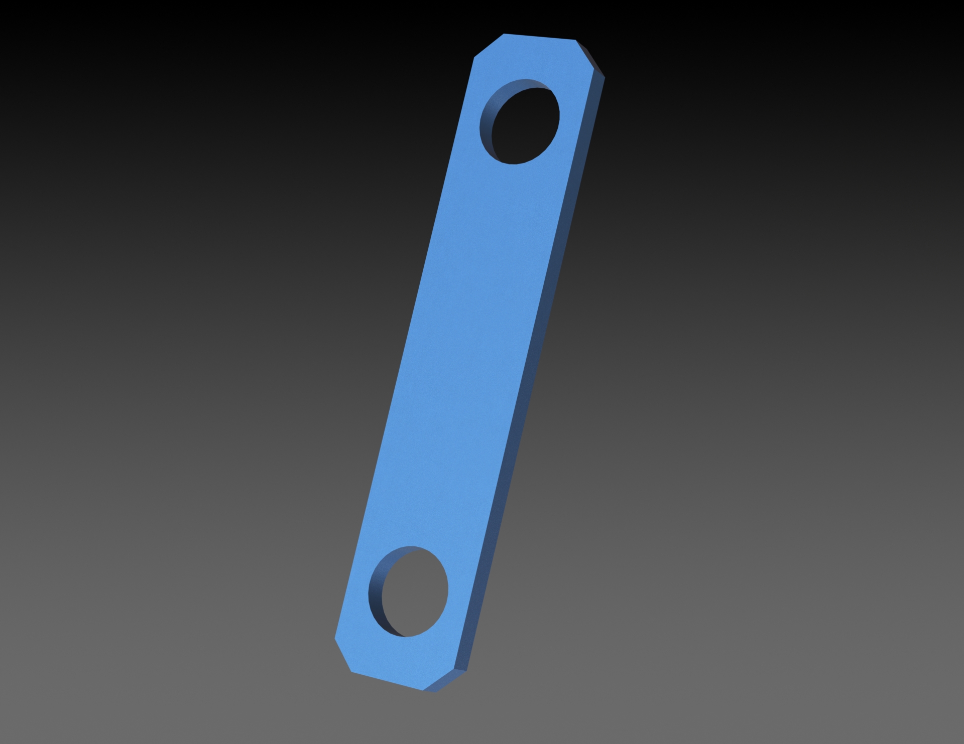
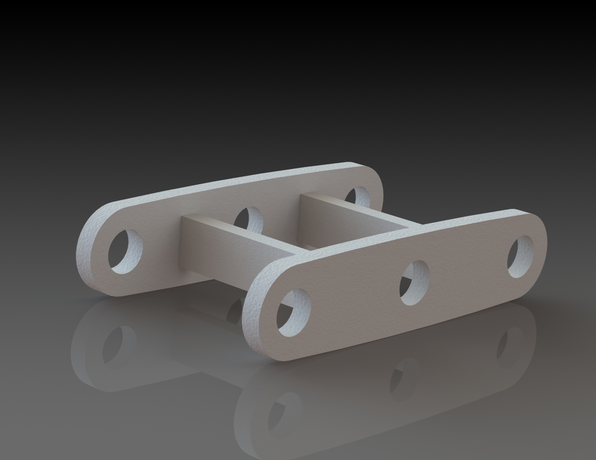
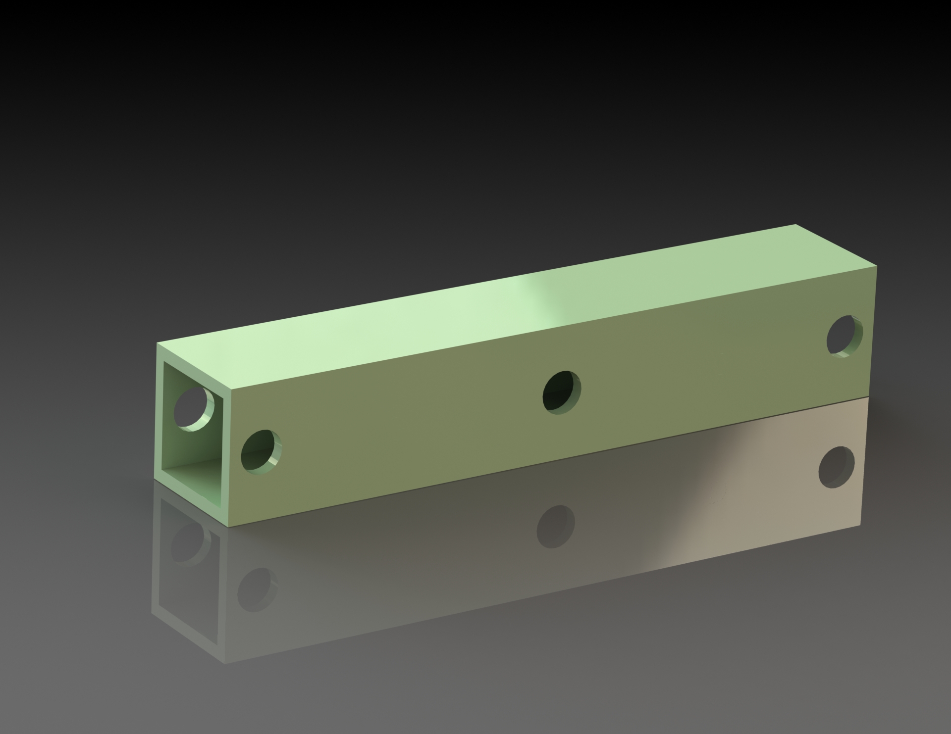
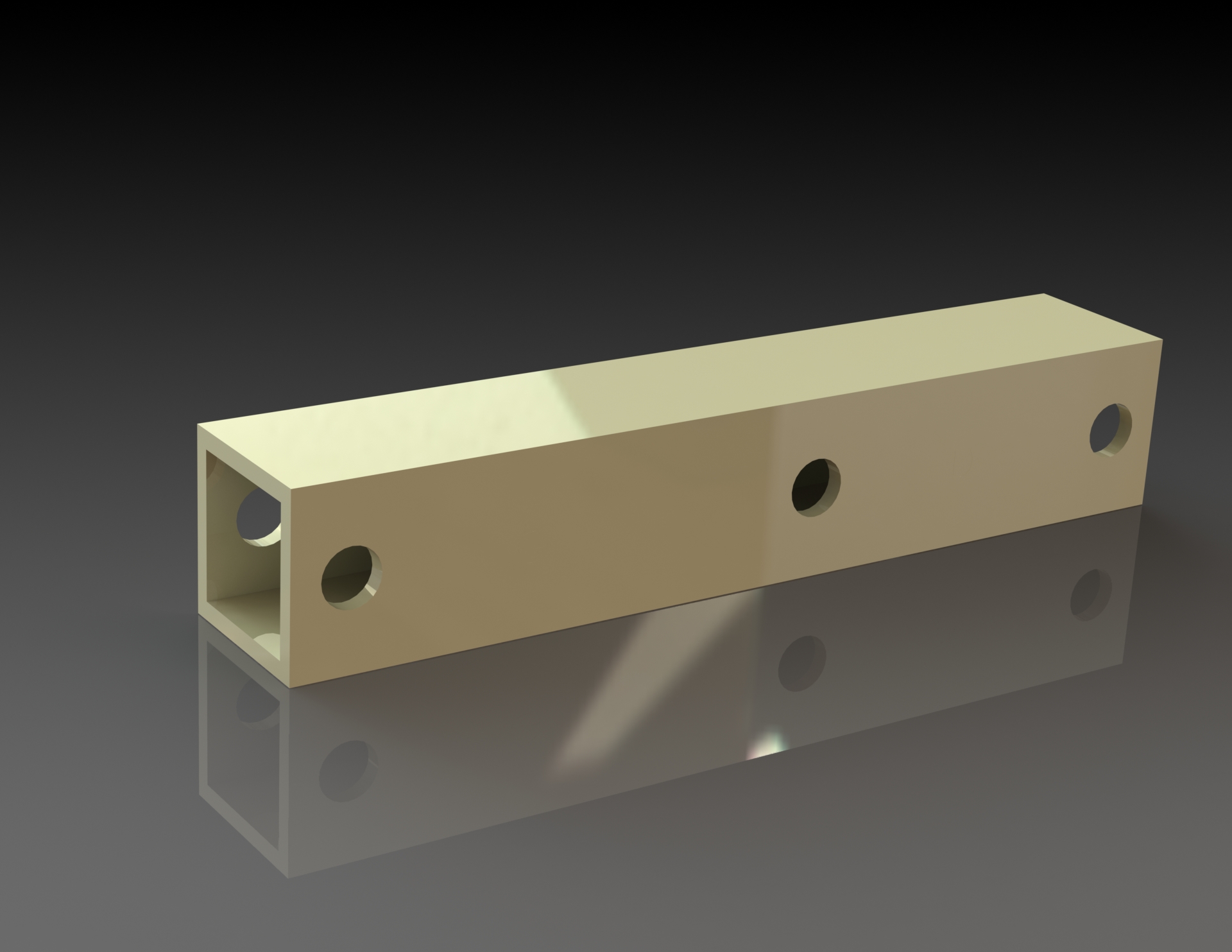
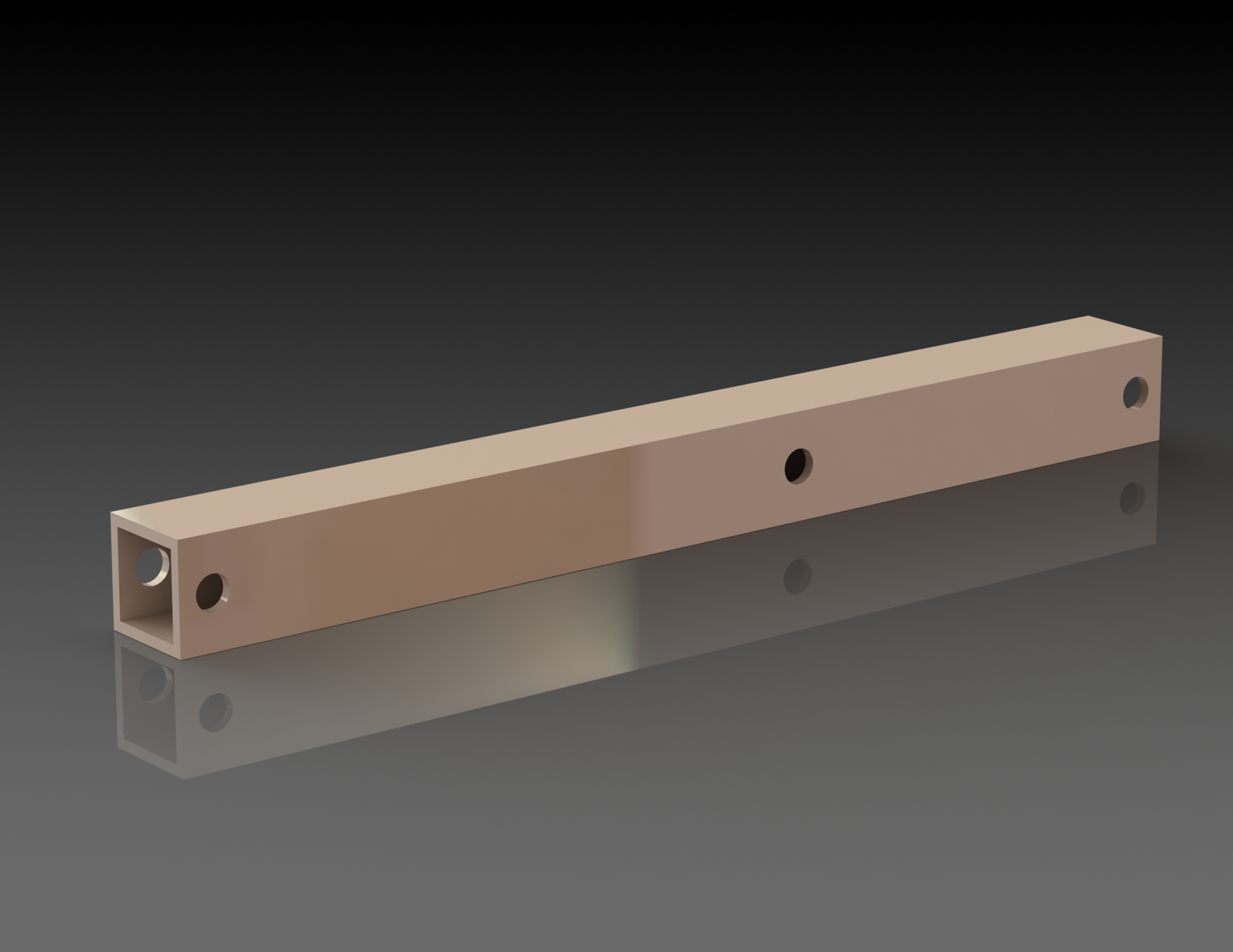
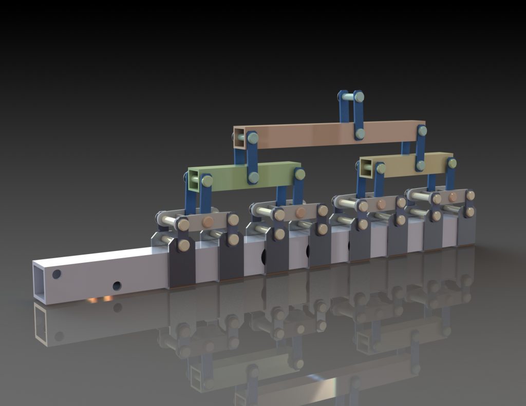
Renderings of the different parts of the assembly
Our solution is to use steel tie-rods, which will be punched and bent if necessary. For the lifting beams, the first 4 will be iso-tensioned and made by laser-cutting a medium plate. The last 3 will be milled from 20x20mm square tube. The axles will be made of steel, turned and assembled with circlips.
Choosing the dimensions wasn’t very complicated, as all we had to do was retrieve the values from the Excel document.
We also made sure that the parts could be fabricated, such as the tie-rods that support the spar, as they have to be made by bending and therefore not be obstructed by the punch. This was not the case with our first model.
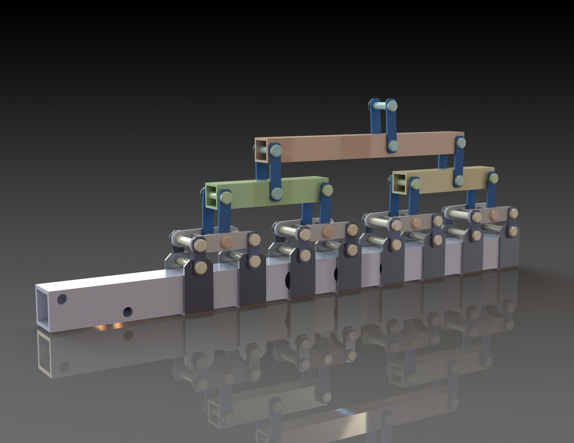
Rendering of our solution
PROJECT 1.3 — PRODUCTION PREPARATION
After the calculations, it’s time to prepare for production. Once the SolidWorks modeling was complete, we produced a report containing various documents to help with production. This includes an exploded view of the assembly, definition drawings of the various parts, phase contracts, manufacturing routings, inspection routings and an assembly routing.
Realized in 5 sessions of 4H + many hours of personal work
To conclude the project, we produced an individual poster to summarize all the skills and concepts studied during the project.
Thanks to this job, I learned how to be the project manager of a team. I was in charge of organizing the project, such as allocating tasks, making sure the project was progressing smoothly, checking the quality of the work carried out and making sure everyone understood the instructions. If not, I explained to team members what was expected of them.
I enjoyed doing this job, but I was careful not to take up too much space and let everyone do the job as they saw fit.
PROJECT 1.3 — TIME FOR PRODUCTION
Now it’s time to put our project into practice. For this purpose, the IUT had us produce their solution, which is fairly similar to ours, except that there are no medium or iso-tensioned parts.
The whole thing was made by the members of my class, and we were all able to produce each piece. In our final session, we assembled the carriage. Seeing it assembled was a real pleasure: seeing the result of our study (even though it wasn’t our solution) was very satisfying.
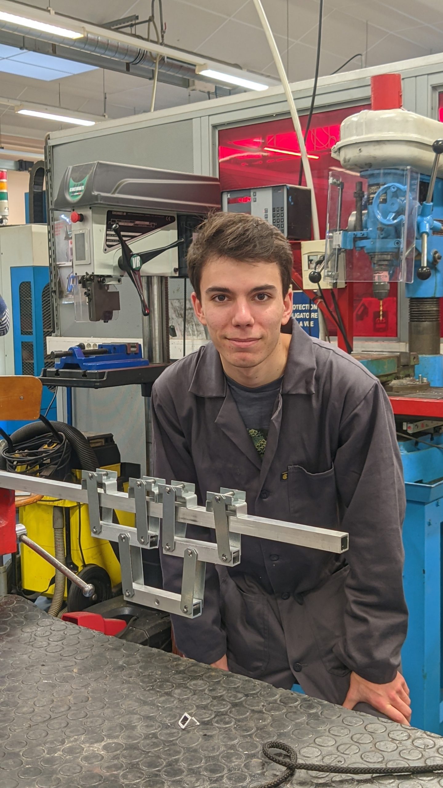
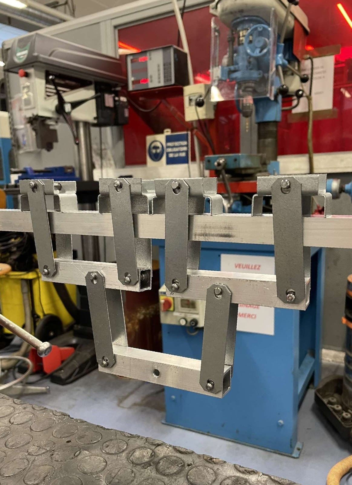
Images of our production (IUT solution)
MY WORK OUTSIDE THE PROJECTS :
Personal and Professional Project – INTERVIEW
Apart from the SAEs, I was able tointerview a person of my choice who had completed at least 3 years of higher education and was still in work. Thanks to the people around me, I was able to meet Eugène Chatillon, who has been a team leader at TRACTEBEL for 5 years now.
This brand-new experience has given me new insights into the professional world. First of all, I learned how to get in touch with someone as part of a professional job. To carry out this interview, I learned to prepare my questions according to the subject but above all according to the profile of the person I was going to interview. To do this, I had to research my interviewee via networks such as LinkedIn, with which I was able to prepare more precise questions about his or her work, length of time in the workforce and student background.
I learned more about my contact’s sector of activity (nuclear) and the company he works for. I was able to make up my own mind about it, and ask myself whether it’s a sector that might interest me or not.
As for practicing an interview, I realized that it wasn’t necessarily easy to talk to someone about their job, and that it required a minimum of experience. Because this activity requires you to be at ease in an exchange with someone you don’t necessarily know well, to be able to take notes and bounce back on what your interlocutor tells you.
However, I can only take positives from this experience. I was able to learn more about the world of work and it opened my eyes to how to find and choose my future career/studies.
Following this interview, I produced a report in which I rephrased my interviewee’s answers and gave my personal feedback on the experience.
EXPRESSION AND COMMUNICATION – SPEAKING
As part of my expression and communication course, we were given the task of preparing an oral presentation to present our 1 semester in the form of the “My thesis in 180 seconds” competition. The constraints we were given were: 1 image, then 1 word and a trace of our work in the form of an image, an assignment, an evaluation…
My presentagtion slide
The oral took place in a lecture hall, so we had to speak loudly, with good intonation and articulation. I found this exercise enriching and it made me realize the effort required when speaking in a large room. What’s more, it enabled me to take stock of what I’d learned/discovered this year, even things outside my studies (passing a new milestone as I entered the world of students and “adults”).
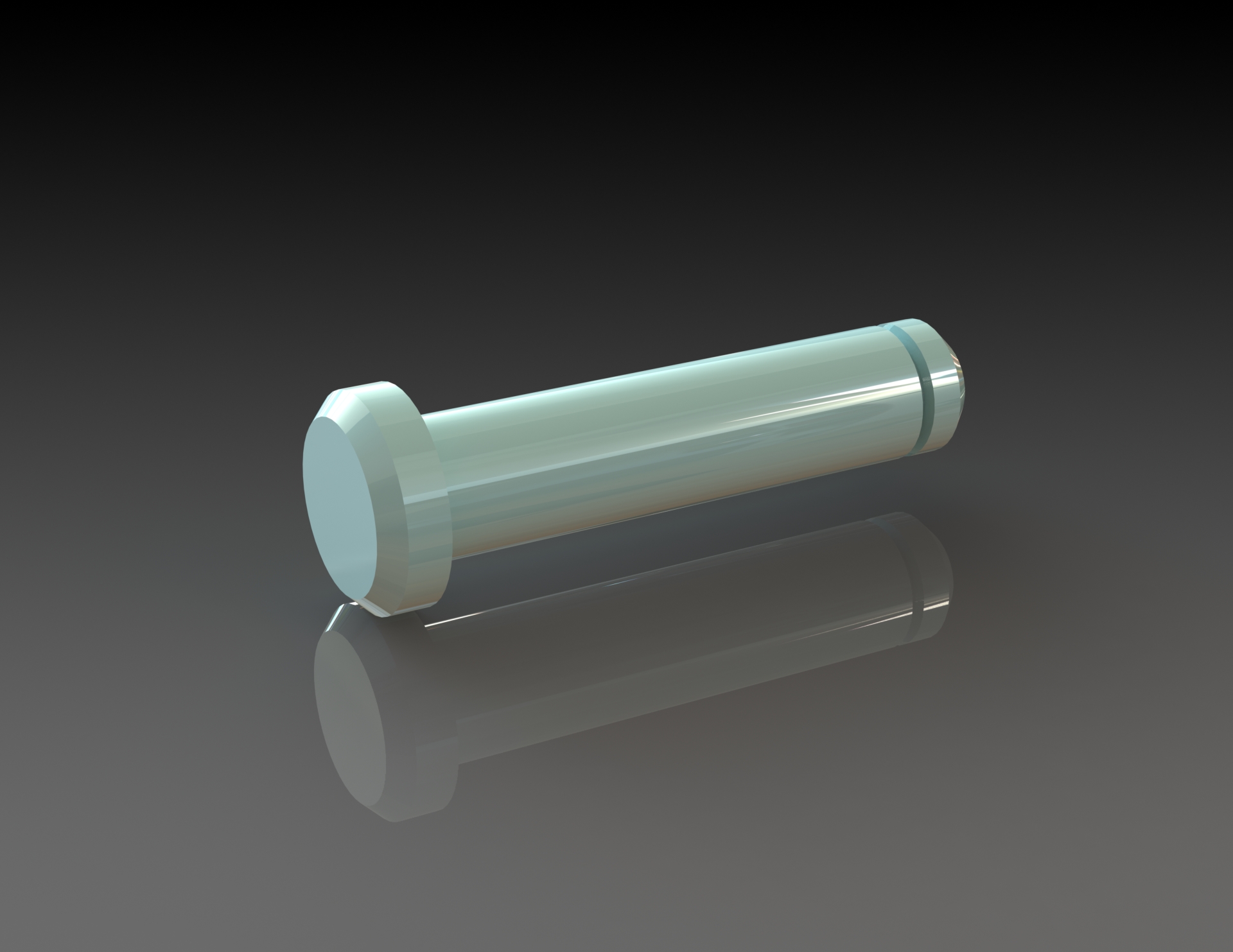
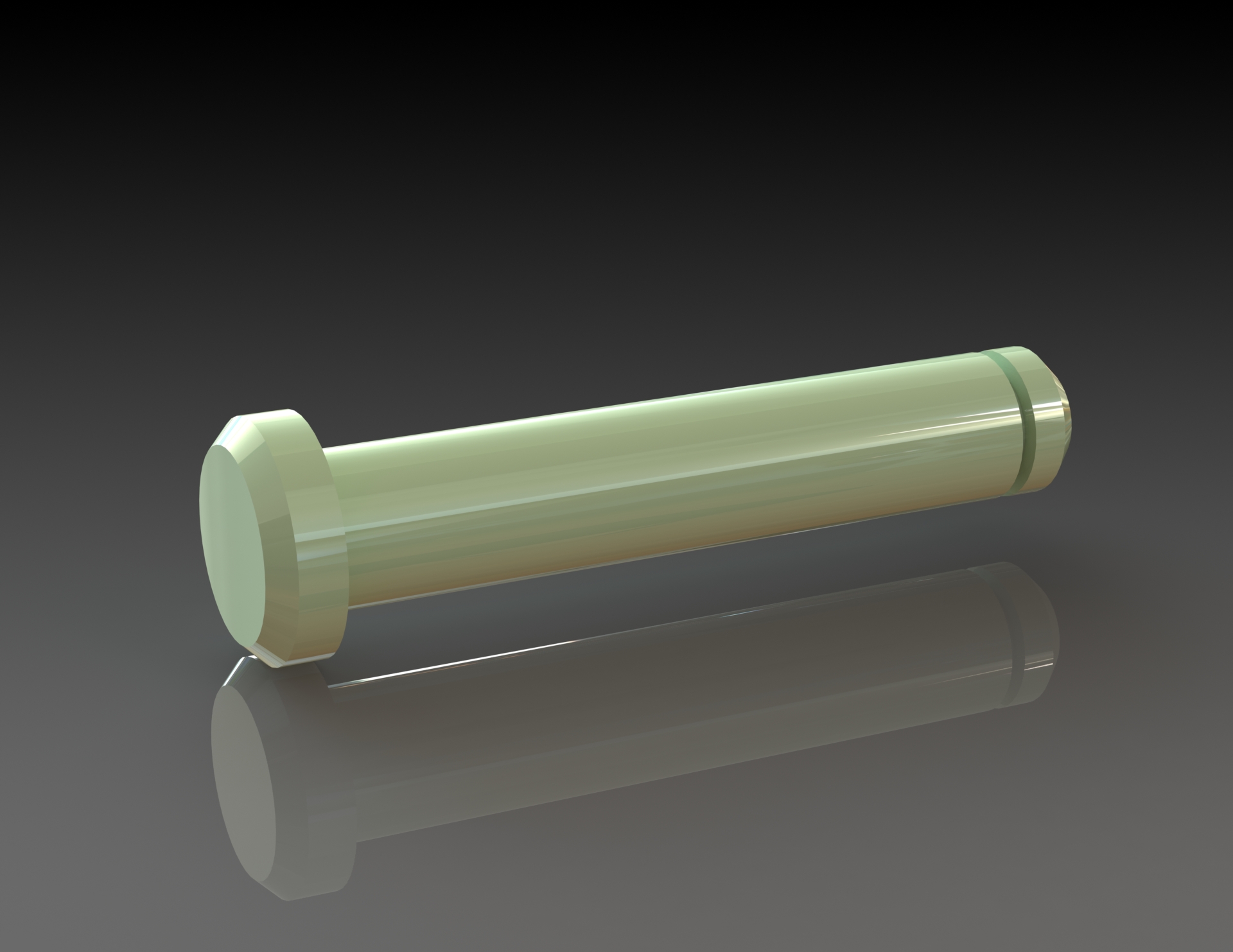
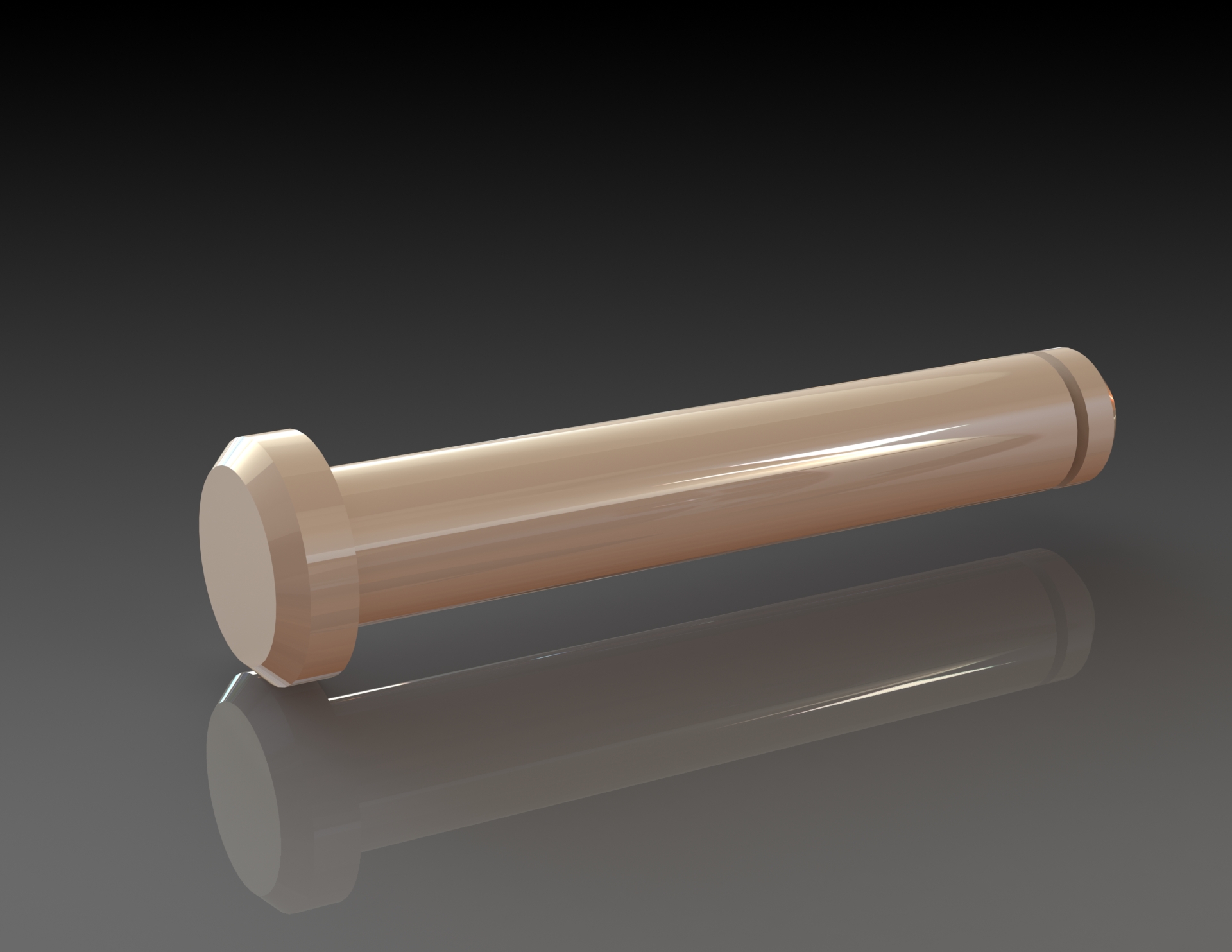
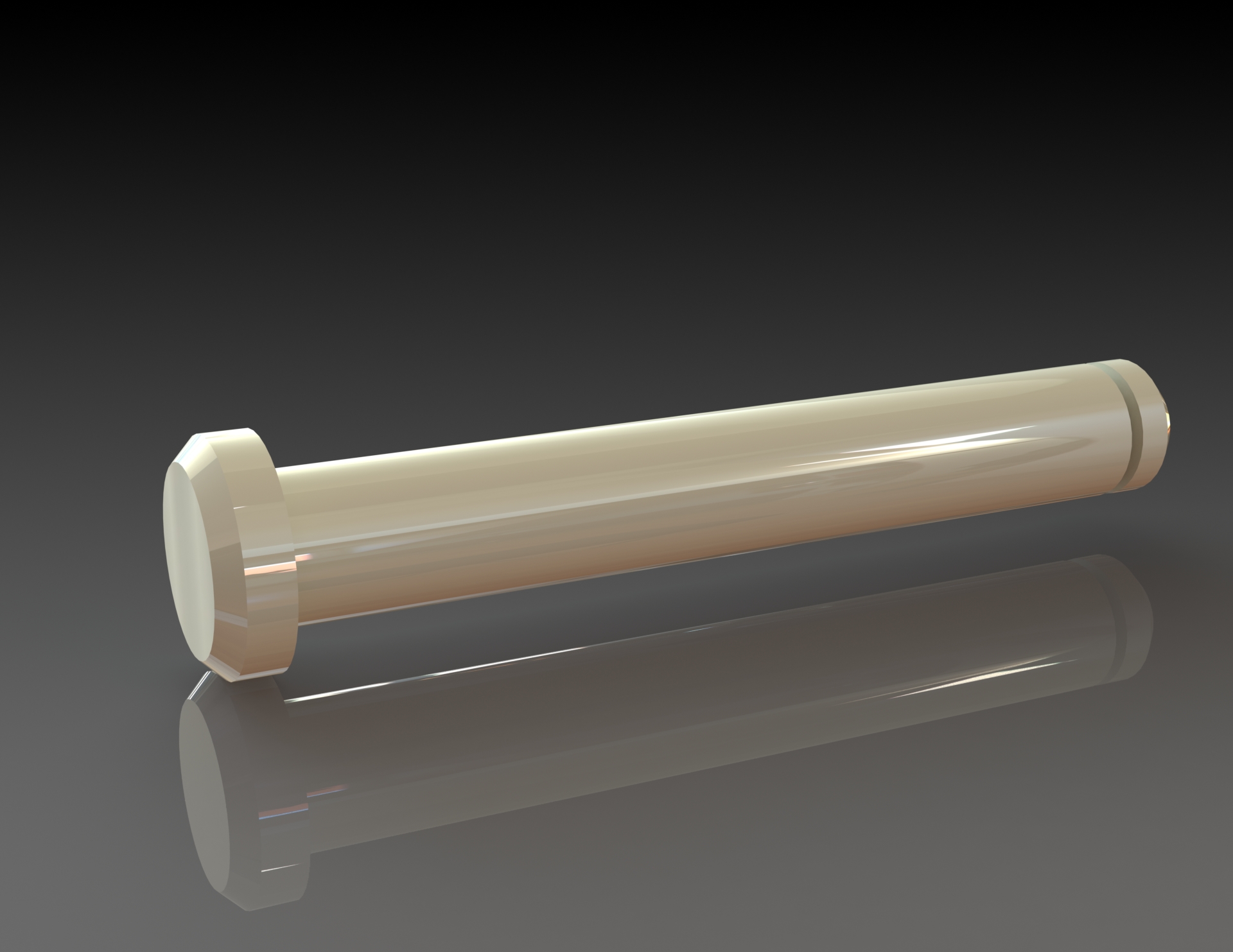
3D MODELING
In my first semester, of course, we had design office sessions during which our teacher acted as engineer. He would give us indications such as a drawing of the overall solution to get a general idea of what the CAD would look like. But also, the possible solutions for creating the links between the different parts (shouldered screw, axis with pressure screw…) and the dimensions to be respected.
Before each design, we carried out calculations to determine the forces at the axes between each body, and then determined the diameter of the axes.
We were free to create whatever design we wanted, as long as the teacher’s instructions were respected.
MY REVIEW OF THE 1ST HALF-YEAR
This semester confirmed my choice of training, which corresponded entirely to what I wanted to learn and discover. These four months have been full of happiness and have pushed me to improve and to pursue my curiosity even further. Following this semester, I’m thinking of doing a work-study program for my 2nd and 3rd years. I’m currently looking for a work-study placement.